As a key component in modern industry and infrastructure, the design concept behind spiral steel pipes goes beyond simply piling up "tubular structures." Instead, it incorporates a systematic engineering approach that integrates materials science, mechanical principles, manufacturing processes, and application requirements. From the pressure resistance requirements of oil and gas pipelines to the shear resistance requirements of bridge pile foundations to the spatial adaptability of building structures, the design of spiral steel pipes consistently revolves around three core elements: "functional adaptability," "structural reliability," and "manufacturing economy," maximizing value through a dynamic balance.
I. Function-Oriented: Defining "Basic Parameters" Based on Requirements
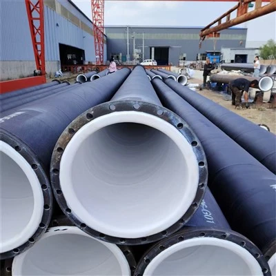
The first step in spiral steel pipe design is to "precisely identify the application." Different application areas place distinct demands on the performance of steel pipes. Oil and gas pipelines must withstand high pressures (typically ≥6 MPa) and resist corrosion from internal media (such as sulfide stress corrosion from sour crude oil). Therefore, design priorities include wall thickness (using hydrostatic testing to infer the minimum wall thickness), internal anti-corrosion linings (such as 3PE coating or epoxy powder coating), and weld fatigue strength. On the other hand, spiral steel pipes used in building structures (such as temporary bridge supports or spatial truss members) place greater emphasis on cross-sectional inertia (affecting bending and torsional resistance), surface treatment (anti-rust paint or hot-dip galvanizing), and compatibility with joint connections (such as flange interface or weld groove design).
This "demand-first" design approach essentially translates "functional objectives" into quantifiable parameters. For example, in long-distance oil and gas transportation projects, designers use fluid dynamics simulations to calculate the internal pressure distribution in the pipeline. Taking into account geological conditions (such as foundation settlement in permafrost areas or thermal expansion and contraction in desert regions), they determine the allowable hoop stress range for the steel pipe. Ultimately, they derive the required height control for spiral welds (typically ≤ 2mm to reduce stress concentration), the optimal ratio of pipe diameter to wall thickness (for example, a DN1000 pipe typically has a wall thickness of 8-16mm), and even accurate weight per meter (to avoid over-limit transportation).
II. Structural Intelligence: The Mechanical Secret of Spiral Forming
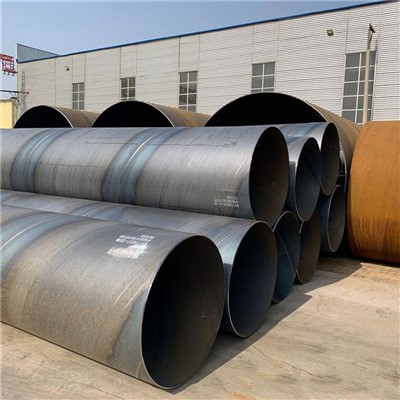
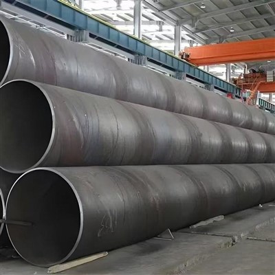
The key difference between spiral steel pipe and straight seam steel pipe lies in its unique "spiral continuous welding" forming process-steel plates are coiled and welded along a spiral line to form the pipe. This process itself embodies ingenious structural mechanics design.
From a mechanical perspective, the spiral weld runs at a certain angle (typically 50°-75°) to the pipe axis. This "oblique load" characteristic ensures more uniform stress distribution in the weld area when subjected to internal pressure. Compared to straight seam steel pipe (where the weld seam is perpendicular to the axial direction, easily becoming a stress concentration point), spiral steel pipe can achieve a 15%-20% increase in circumferential load-bearing capacity (measured data). This makes it particularly suitable for large-diameter (DN1200 and above) and high-pressure long-distance pipelines. Furthermore, the spiral forming process preserves the fiber continuity of the steel plate (unlike straight seam steel pipe, which requires longitudinal cutting and splicing of the steel plate), significantly improving overall impact resistance and fatigue life.
The choice of helix angle also needs to be considered during design. A too small angle will make it difficult to align the steel plate edges during forming (affecting weld quality), while a too large angle will increase the load on the plate rolling machine and reduce the radial stiffness of the pipe. Engineers typically use finite element analysis (FEA) to simulate stress distribution at different helix angles to ultimately determine the optimal angle range that ensures both forming efficiency and structural strength requirements.
III. Manufacturing Adaptation: Optimizing Producibility within Constraints
Design cannot be divorced from manufacturing realities. The design concept for spiral steel pipe must include a thorough consideration of process feasibility. For example, the selection of steel plate raw material must balance strength and weldability. While high-strength pipeline steel (such as X80) can reduce wall thickness and thus material costs, its high carbon equivalent requires strict control of heat input during welding (to avoid cold cracking). Therefore, a wider "welding process window" is reserved during design (for example, by increasing the thickness of the groove blunt edge or adjusting the current and voltage parameters).
Furthermore, transportation restrictions for large-diameter spiral steel pipe (for example, the maximum pipe diameter for road transportation is generally ≤3m, and pipes exceeding this limit must be manufactured in sections and then welded on-site) can also negatively impact the design. If the project requires a single, extra-long pipe (such as an offshore platform support structure), the designer may choose a "segmented spiral + flange connection" solution. By optimizing the flange hole layout and sealing surface angle, this solution meets transportation requirements while ensuring on-site installation accuracy.
Of even greater note is the incorporation of "green manufacturing" concepts: Modern spiral steel pipe designs prioritize recyclable materials (such as Q235B carbon steel) and reduce steel usage by optimizing wall thickness (for every 1mm reduction in wall thickness, the weight per meter decreases by approximately 6%-8%). Controlling weld reinforcement not only affects stress distribution but also reduces the amount of grinding required during subsequent anti-corrosion coating application, indirectly reducing carbon emissions.
Conclusion: Engineering Philosophy in Dynamic Balance
The design of spiral steel pipe is essentially a process of finding the optimal solution between "functional requirements," "structural safety," and "manufacturing cost." This requires engineers to precisely control material properties (for example, knowing the yield strength of Q345B steel is 345 MPa, corresponding to the allowable stress for different wall thicknesses), as well as a deep understanding of process limitations (such as the maximum coil thickness limit of the spiral welding machine). Furthermore, a "full lifecycle" perspective is crucial (from production, transportation, installation, to operation and maintenance).
When a spiral steel pipe withstands high-pressure transportation in a desert oil and gas pipeline, resists the impact of waves in the pile foundation of a cross-sea bridge, or supports the spatial structure in the dome of a stadium, it is the crystallization of this "rational calculation" and "engineering wisdom" that is condensed behind it - this may be the core value of the spiral steel pipe design concept: using scientific methods to make metal components a reliable bridge connecting needs and reality.